The EOIR sensor type camera takes an image of whatever is in its field of view (FOV). You must set up the orientation of the FOV properly so that objects appear as they actually are. When the EOIR sensor is attached to moving objects, such as satellites and aircraft, the attitude of the object will also impact the orientation of the EOIR FOV. However, when the EOIR sensor is on a facility, orientation of the FOV is based only on the pointing of the sensor, since facilities are fixed in their position. The following steps outline the process for aligning an EOIR sensor on a facility to track an object of interest.
- In the Analysis menu, select Analysis Workbench.
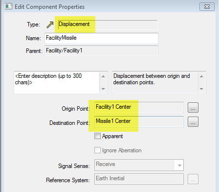
- Click the Create new Vector icon.
- Create a Displacement vector from your Facility object with the EOIR sensor to your object of interest, in this case a missile:
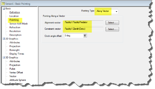
- Open the properties of the facility's EOIR sensor. Under Basic > Pointing, set the Pointing type to Along Vector. Set the Alignment vector to the vector created in step 3 and the Constraint vector to the Facility Zenith (Detic):
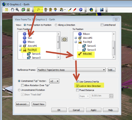
- You can verify that the synthetic scene produced by EOIR matches the 3D model orientation by orienting the view in the 3D Graphics window correctly. To do this, click the View From/To button in the 3D Graphics window. Set the From position to the facility and the To position to the object of interest. Then select the Lock in View Direction check box. Once you apply this, you can zoom in inside your 3D Graphics window to match the field of view of the EOIR sensor.