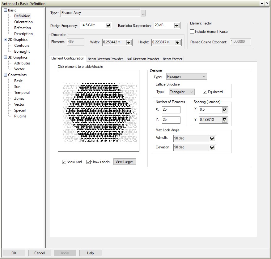
Ideally, the spacing (Dx) between radiating elements in a phased array should be as follows:
Dx < l/(1+sinqs)
Where qs is the maximum scan/look angle e.g. for qs = 90 degrees, Dx < l/2
Scanning above this angle will cause grating lobes which is an artifact where strong radiation occurs in an unintended direction.
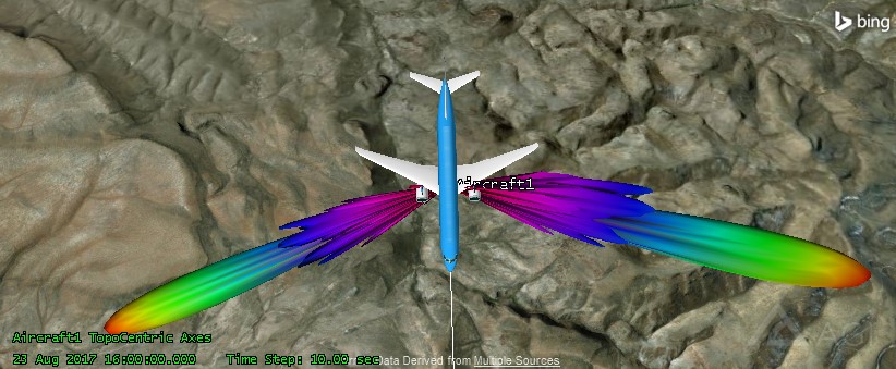
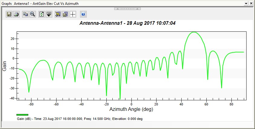
With l/2 spacing between radiating elements, we have the following when scanned to 50 degrees:
1. Full Field of View (
qs = 90 degrees)
2. Main Lobe at 50 degrees
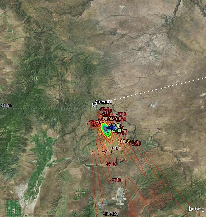
3. 2D Antenna Gain Contours shown
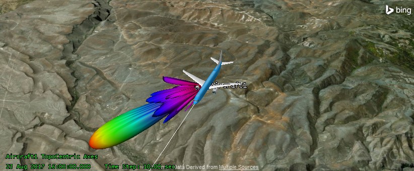
4. 3D Beam Pattern shown
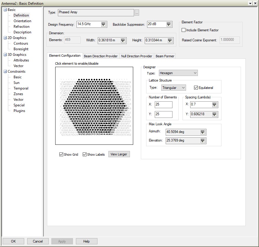
With 0.7
l spacing between radiating elements, we have the following when scanned to 50 degrees:
1. Limited Field of View (
qs = 25.3769 degrees in elevation angle)
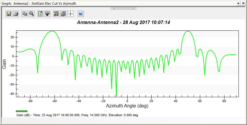
2. Main Lobe at 50 degrees with grating lobe
3. 2D Antenna Gain Contours shown
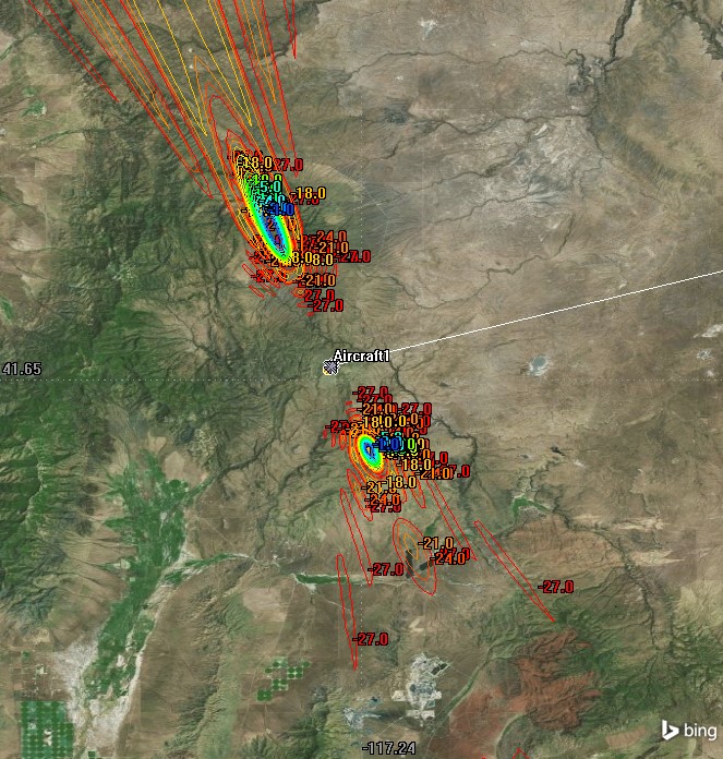
4. 3D Beam Pattern shown with grating lobe