To reference the aircraft's starting point, you first need to make a custom point using STK's
Analysis Workbench capability to define where the starting point is. Then you can reference the NED coordinates to this point.
Follow these steps to create the reference frame.1. Open Analysis Workbench, which is under the Analysis menu tab in STK, and select the Vector Geometry tab.
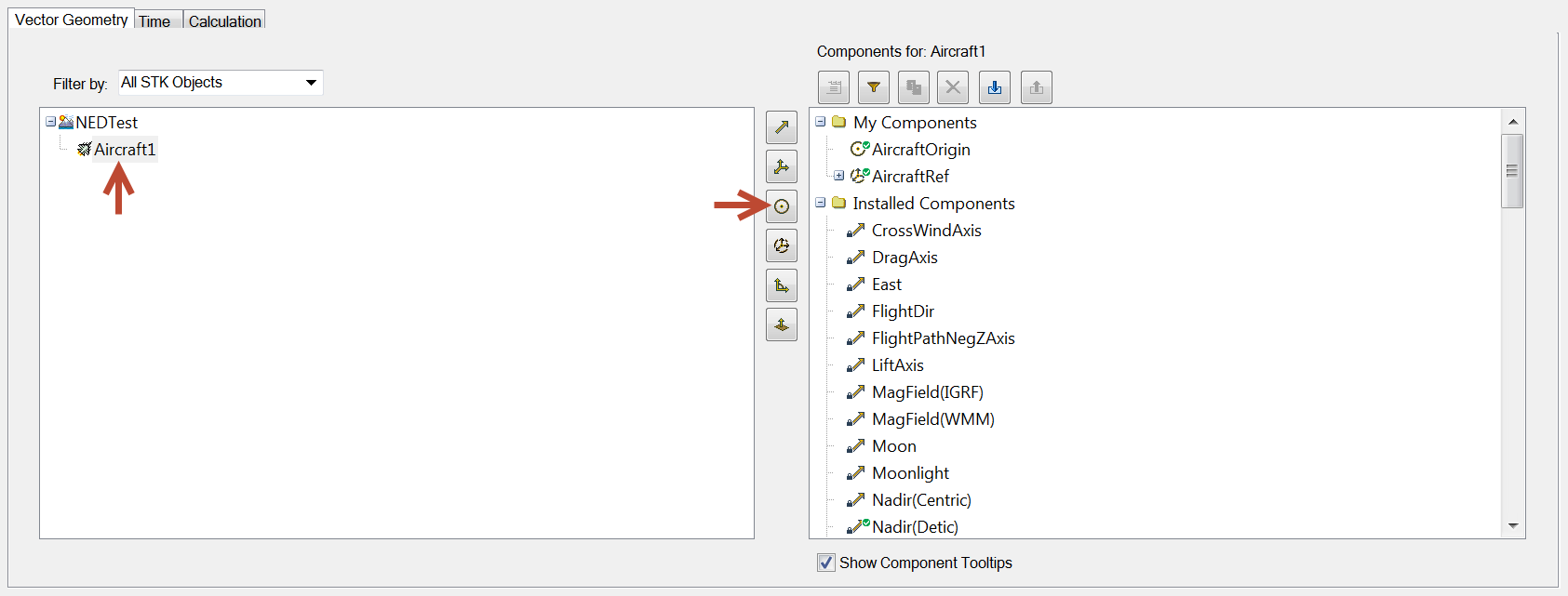
2. Ensure that your aircraft is selected in the box on the left and click the
Create new Point icon.
3. In the dialog box, set the following values:
Type: Fixed at Time Instant
Name: [Whatever you want here]
Reference Time Instant: [AircraftName] AvailabilityStartTime
Source Point: [AircraftName] Center
Reference System: Earth Fixed
4. Click OK to set this. It should show up under the folder My Components.
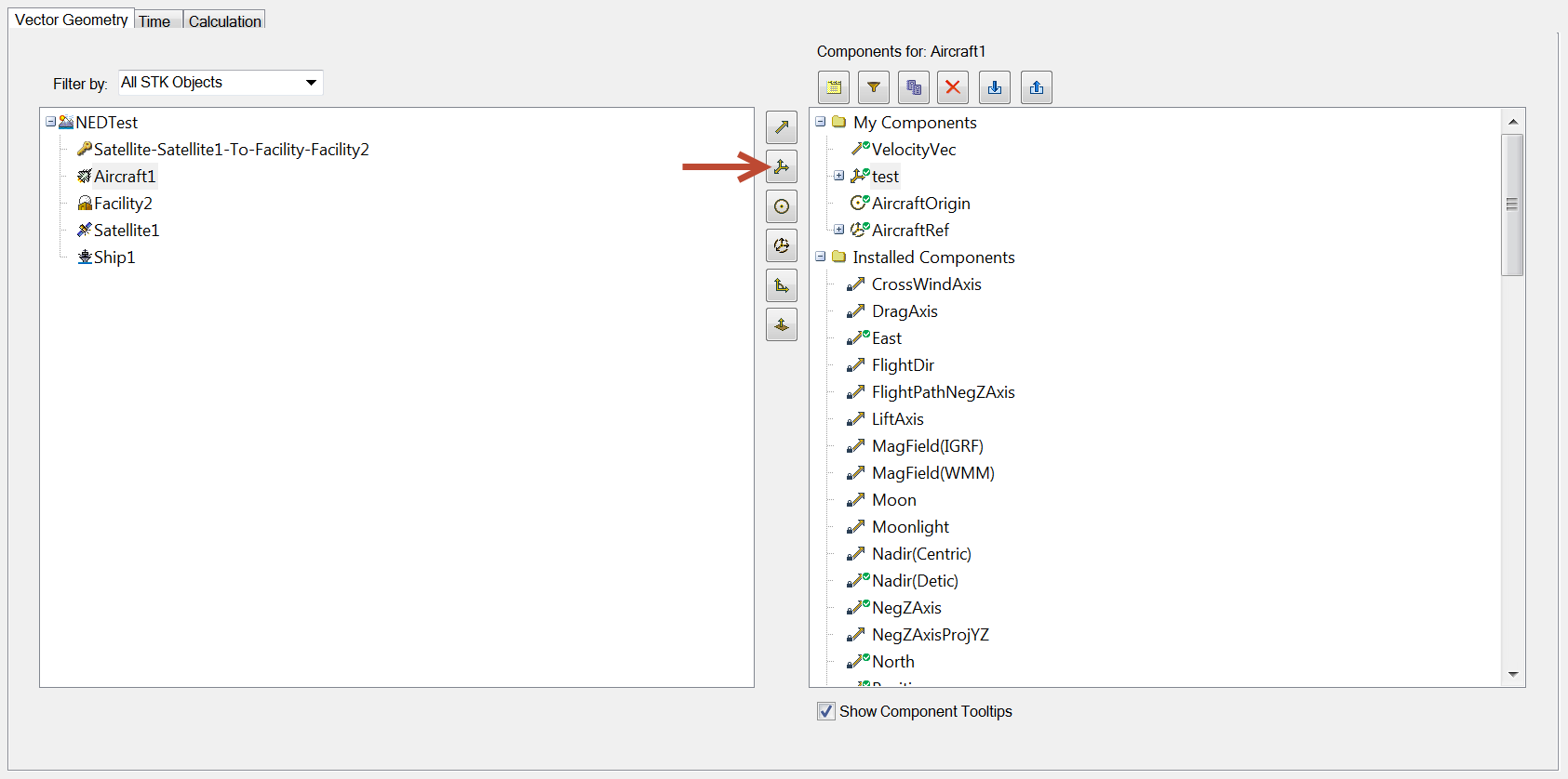
5. Next in Analysis Workbench, click the
Create new Axes icon.
6. Set the following parameters:
Type: Aligned and Constrained
Aligned Vector: [Aircraft Name] North
Aligned Vector Orientation: Cartesian
X: 1
Y: 0
Z: 0
Constrained Vector: [Aircraft Name] East
Constrain Vector Orientation: Cartesian
X: 0
Y: 0
Z: 1
7. Click OK.
This will create the NUE coordinate frame you are looking for at your aircraft.
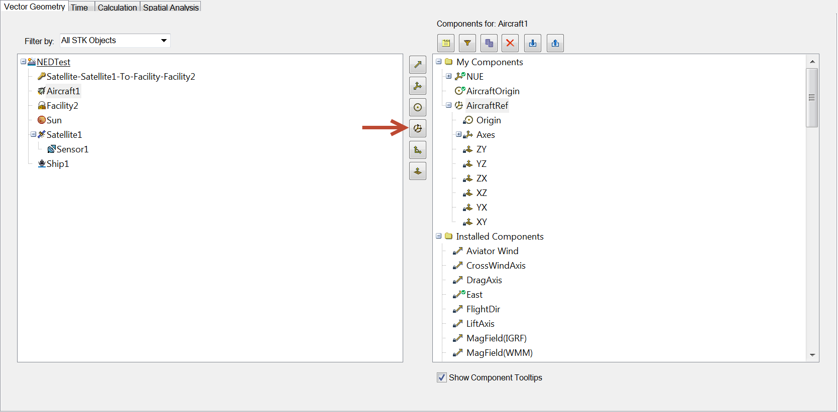
8. Next, click the
Create new System icon.
9. Set the following vales:
Type: Assembled
Name: [Whatever you want here]
Origin Point: [AircraftName] [Name of previously defined point]
Reference Axes: [AircraftName] [Name of previously defined axes]
10. Click OK.
Create a report of the x, y, and z points in the NUE coordinate frame1. Right-click the aircraft and select Report & Graph Manager.
2. Create a new report style. Select the Points Choose System data provider and expand it. Select Center and expand that. Select the following parameters to move to the Report Contents section:
Time
x, y, and z (North, Up, East coordinates)
Magnitude
Velocity x, y, and z
3. Next find the Vector Choose Axes data provider and expand it. In that tree, you should see Velocity (CBF); expand that.
4. Select Derivative x, y, and z, which will be the derivative of your velocity vector, the acceleration. Move these to the Report Contents panel. You can rename these to Acceleration instead of Derivative for clarification, if you'd like.
5. Highlight the provider in the right box under Report Contents and click the Options button at the bottom. Rename the title if you wish.
6. Click OK to return to the Report & Graph Manager.
You can then generate the report (click the Generate button) you just created, and a dialog box will appear to prompt you for a selection of axes and a system. Click the Axes and the System you created earlier (under My Components). This will then generate a report with the x, y, and z points in reference to the aircraft's initial point.

