Assumptions:You or someone else already computed body mask files using the
AzEl Mask Tool .
1. Right-click the parent object (Ship, Aircraft, etc.) and select Analysis Workbench.
2. Select the Spatial Analysis Tab.
3. Select

to create a new Volume Grid, and set the following parameters:
• Type: Spherical
• Name: SimpleSphere
4. Reference System: Leave this value as the default (should be the parent object’s Body).
5. Click

and set the minimum and maximum coordinate bounds and the number of steps:
• Azimuth: between 0 and 360 deg with 36 steps
• Elevation: between -90 and 90 deg with 18 steps
• Range: between 30 and 50 m with 1 step
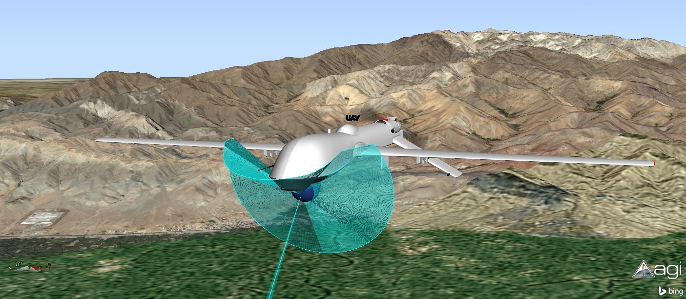
Note: The minimum and maximum values will be different for every parent object, depending on the object size and the body mask projection distance. For a UAV, start with smaller values (3 to 5 m with 1 step).
6. Click
OK twice to apply the changes and create the new grid. STK will add the
SimpleSphere grid under My Components.
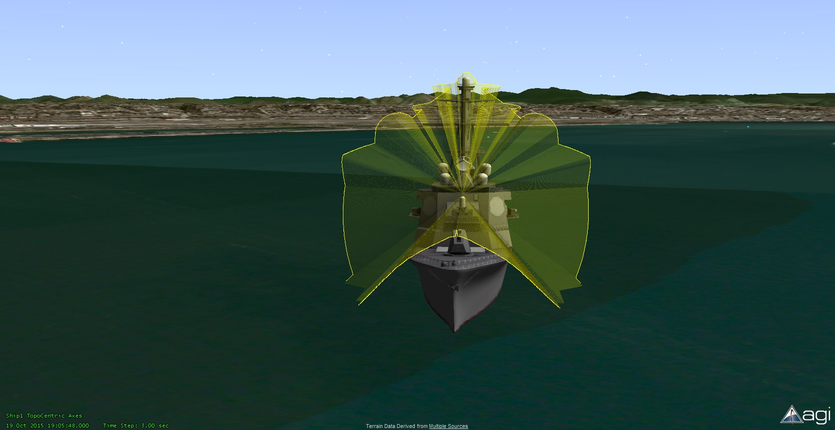
7. Highlight the body mask sensor under the parent object.
8. Select

to create a new Volume Grid and set the following parameters:
• Type: Constrained
• Name: BMSK_Constrained
9. Click the Reference Grid ellipsis  to bring up Volume grid selector from Analysis Workbench. Select your parent object on the left and SimpleSphere on the right. Click OK to assign the selection.
10. Click Spatial Condition to bring up the Spatial Condition selector from Analysis Workbench. Select your body mask sensor on the left and Visibility on the right. Click OK to assign the selection.11. Click OK to apply your changes and create the new grid. STK will add the
BMSK_Constrained grid under My Components.
12. Click
Close to dismiss the Analysis Workbench.
13. From the Insert STK Objects menu,
select Volumetric ( ) on the left and Define Properties on the right.14. On the Volumetric1 BasicàDefinition page, click next to Volume Grid to bring up the Volume Grid selector from Analysis Workbench.
Note: STK's Analysis Workbench capability displays the STK objects on the left and the Spatial Analysis components on the right.
15. Select the body mask sensor on the left and BMSK_Constrained on the right.16. Click OK to assign the selected volume grid to Volumetric1.17. Click Apply to assign all selections to Volumetric1.
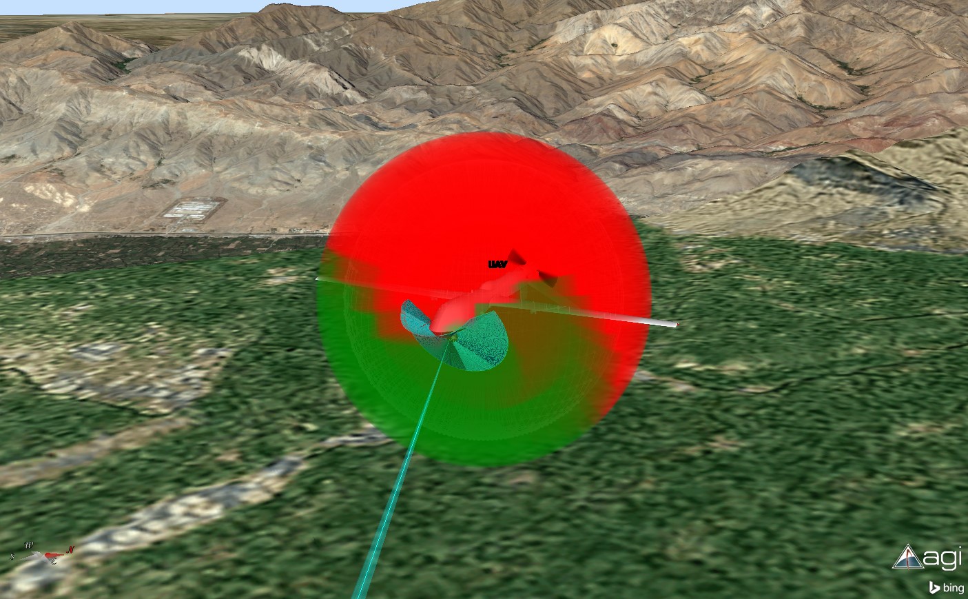
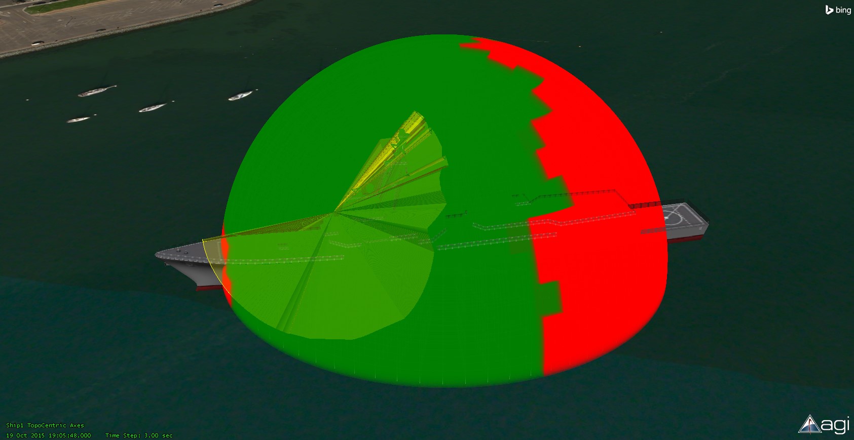
Note: The SimpleSphere grid is now visible in the 3D Graphics window. This illustrates the extent of space covered by the grid as well as granularity of the grid.
18. Right-click Volumetric1 in the Object Browser and select VolumetricàCompute to initiate evaluation of volumetric data over time and across the grid.
Note: Once the computation is completed, the entire grid volume will be filled with the color(s) specified on the Volumetric1 3D GraphicsàVolume page.
Other tips and tricks:In order to increase fidelity, increase the number of grid points in the SimpleSphere grid and then recompute. This may increase computation time.If it isn’t necessary to display the body mask volumetric graphics for the entire analysis interval, you may want to create a new Fixed Duration Time Interval for the Scenario Object and then utilize it in the Volumetric1 Basic à Interval page.