A good starting place for understanding the body mask file is the help description found here.
This also includes sample files, which are a good starting place to define your own files and will be used in this explanation. There is also a step-by-step tutorial on generating body mask files.
The BMSK file defines areas of exclusion or inclusion to be applied to a sensor mask. It is defined using an offset from local axes, which are specified in the header fields LocalZ and LocalX. Take a look at a sample file. Below is an explanation of this sample.
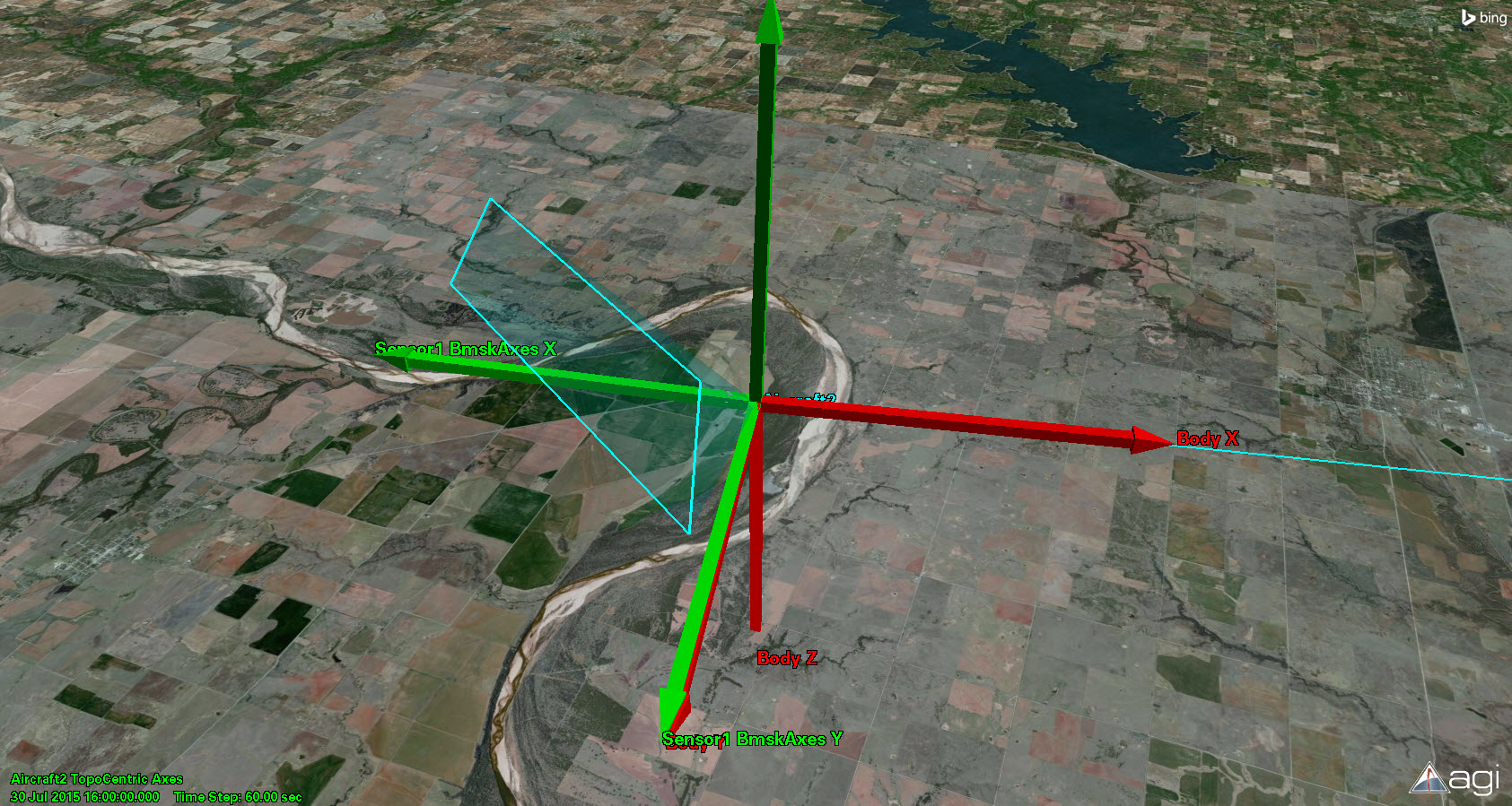
If you look at the first group in the file, you will see that the file defines an exclusion area and the LocalZ is -1 and the LocalX is -1. This tells STK how the axes are defined relative to the parent object body axes of the sensor, which in this case are the red axes of the aircraft in the picture below. I created new green axes in the Vector Geometry Tool, with the +X body axis in the -X direction and the +Z axis in the -Z direction. I then took a couple of azimuth and elevation angles from the file and created vectors that represent the direction of the exclusion boundary wall. You can see in the picture that the purple vectors, which represent az/el pairs from the file, intersect the boundary wall of an exclusion zone.
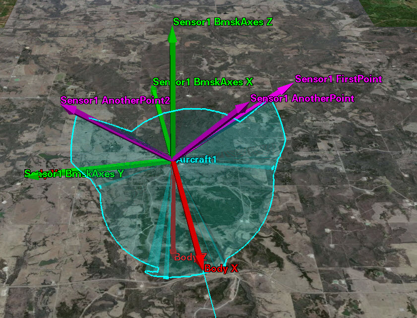
For a valid boundary, you need enough az/el pairs to form a polygon projected onto a sphere. To show this, I created a very basic BMSK file (attached) with one exclusion zone containing four points. You can see in the picture below that the box drawn is an area of exclusion, but any other direction is seen by the sensor. The level of detail you want in the mask dictates how many pairs you should define. Just think of the az/el pairs as points on a sphere; connecting the pairs together in consecutive order creates the boundary. The boundary wall starts at the first point defined and continues to the last point that then connects back to the first point.
Note: It is best to create more than the minimum number of points per inclusion/exclusion area, otherwise analysis results, such as for access, might be inconsistent. An az/el pair for each degree of angle along the polygon seems to be a good resolution.