Orbit Determination Tool Kit (ODTK), despite its name, can be used for applications that do not involve orbits! This example shows how you can use ODTK to perform geolocation of a ground-based emitter using an airborne platform. Included are insights into the limitations of this implementation. An example scenario is also attached. In order to run the attached scenario, you must amend all file paths in ODTK to point to your own local path. If running the included Python script, you must install AGI's STK Python API.
The steps below describe the general process of setting up a combined STK and ODTK scenario to accomplish this geolocation task.
- In STK, create your aircraft routes. You can use the simple Great Arc propagator or integrate a full-performance model and mission using STK's Aviator capability. For simplicity, the attached example uses two Great Arc aircraft flying in a straight line. You will evaluate the difference in quality of the geolocation solution between using just one aircraft for estimation and using both.
- Export both aircraft ephemerides to a standard STK *.e file. This will provide the truth route for ODTK. If aircraft ephemeris covariance is available, you can add it manually to the *.e file. ODTK will consider aircraft covariance during the estimation process if it is available.
- You will simulate TDOA measurements on board each aircraft by using antennas placed on each wingtip. Open ODTK and add two satellite objects. Each satellite will simulate a single antenna. Set the EphemerisSource to "Reference Trajectory" and supply the ephemeris file of one aircraft exported in step 2 to both satellite objects. Set the Covariance Source to None. As of version 7.6, ODTK cannot directly estimate the aircraft's route.
- Add an antenna object to both satellites. Set the Phase Center Location to the location of each wingtip relative to the aircraft's body center. For this simulation, place one antenna at (0, -20, -4) meters in the body frame and the other at (0, 20, -4) meters.
- Add a transponder object to both satellites. Set the Type to Relay and set the DefaultAntenna to the corresponding antenna that you created in step 4. As of version 7.6, ODTK requires a transponder object to properly respect the antenna phase center locations when simulating and processing TDOA measurements.
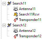
- On one satellite object, add a tracking instrument object. Since you are using TDOA measurements from a vehicle, remove all the default measurement statistics and add SB TDOA. This tells ODTK that this aircraft is only capable of generating and processing TDOA measurements. Additionally, set the bias half-life to something small, like 0.001 minutes. The resulting Object Browser should look like this:
- Repeat steps 3-6 for a second pair of satellite objects for the second aircraft ephemeris.
- Add a Tracking System, a Facility, and an Emitter nested into each other. Set the nominal facility location and location errors as desired. The example uses AGI's HQ in Exton, PA, with SouthSigma and EastSigma values of 5 km.
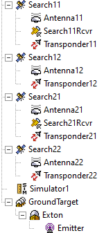
- Add a Simulator object to generate measurements. Set the simulator StopTime to the earliest aircraft ephemeris stop time. In the tracking strand list, select only the tracking strands that correspond to measurements onboard the same aircraft since you are not simulating TDOA measurements between different aircraft. The completed simulation setup should look similar to this:
- Run the simulator. The simulator will deviate the nominal facility location according to the location error statistics and generate measurements relative to that deviated location.
- A data product list called Default.dpl has been included with the example. Load it into the Static Product Builder and generate the MeasNanosec and SimExport reports to view the results of the simulator run. Note the Latitude, Longitude, and Altitude of the deviated facility from the SimExport report and load the coordinates back into an STK object for visualization if desired.
- Add a Filter object to ODTK. Use the HigherOrderCorrections Mitigationmethod Underweighting to limit the power of each measurement to help in preventing filter divergence. Run the filter to use both aircraft trackers and create a geolocation solution.
- Use the installed State Difference Tool using the output *.filrun file as the target and using the simulator *.simrun file as the reference to view how well the filter was able to recover the emitter's position.
- Generate the FilExport and DiffExport reports in the Static Product Builder and export them to an Excel file. If desired, view the DifferencedFacLocGraph and the DifferenceFacLocTopoReport to view the results graphically within ODTK. You will use these data products to import back into STK for an integrated visualization environment.
- Return to the filter and limit the filter's tracker list to just one tracker. Repeat steps 12-14 to evaluate geolocation using a single tracker.
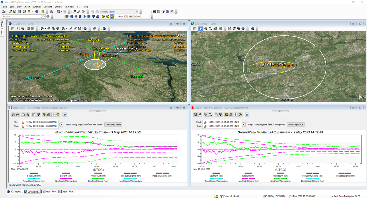
- With STK open, run the ParseODTKResults.py script to import the data from filter and differenced exports into STK as external data. Altogether, this script creates a visual representation of the filter's geolocation estimate and the final uncertainty ellipse into the 2D and 3D graphics windows as well as adds time-dynamic uncertainty and state estimation error data to the scenario for reporting and graphing. The uncertainty and state estimation error is used to create the same graph as the DifferencedFacLocGraph as ODTK.
You're done! You have successfully designed an aircraft TDOA mission in STK, simulated and processed measurements in ODTK, and brought the results back into STK for visualization. As expected, two aircraft performing TDOA generates a more refined geolocation solution than one aircraft. In both cases, the actual emitter location falls within their respective uncertainty ellipses.