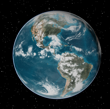
Accurate cloud modeling is an important aspect of many Electro-Optical and Infrared (EOIR) simulations. With the Ansys Systems Tool Kit® (STK®) application, you can model clouds both analytically in an EOIR sensor scene and superimposed visually onto a 3D globe. However, since analysis and visualization of clouds require different file formats in the STK software, there can be discrepancies between the clouds seen on the globe and those shown in the sensor scene. This article describes a simple procedure for converting cloud maps (stored in CSV format) to usable images (referenced by a CLD file).
The procedure for converting from CSV to CLD requires an intermediary file, commonly saved as a JPG file.
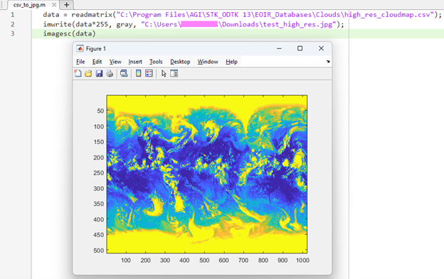
1. In MATLAB, run the following two lines of code:
data = readmatrix(<path to *.csv>);
imwrite(data*255, gray, <path to desired output folder>\image_name.jpg);
- You have the option to add a third line of code to visualize the clouds directly in MATLAB:
imagesc(data)
2. In a text editor, create a new text file with just one line:
10 Oct 2025 19:00:00.000 image_name.jpg
- This could be the start time of your scenario, but it can be any time you like. It will define when the clouds first appear in the STK application.
- You can also add more times in subsequent lines with different cloud models if you want the clouds to change over time.
3. Save that file as a CLD file in the same location where you saved the JPG file.
4. Open the STK Globe Manager by clicking the following button in the 3D Graphics window:

5. In the Globe Manager, right-click Clouds.cld and select "Change Clouds".
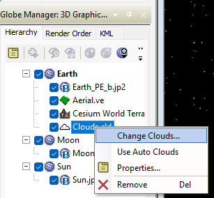
6. Browse to and select your new CLD file. You should now see the clouds in the 3D Graphics window!