Capability required:
Analysis WorkbenchYou can set up a 3D view that:
- stays centered on a foreground object.
- keeps a background object in view.
- does not create a view path.
- does not use the 3D Camera Control toolbar.
Follow these instructions:
- Launch STK and open the scenario that contains the two objects for which you want to create this type of 3D view.
- Decide which object will be in the foreground (call it Object A) and which object will be in the background (Object B).
- Create a vector from A to B; you can use the To Vectors folder. Open Analysis Workbench, select the Vector Geometry tab, highlight Object A on the left, and click
 to create a new vector. Set the following values:
Type: Displacement
Name: ObjectA_To_ObjectB
Origin: ObjectA Center
Destination: ObjectB Center
Click OK to return to the Vector Geometry Tab.
- Click
 to create new axes and select Aligned and Constrained as the Type. The rest of your settings depend on your specific view need, whether to have a level horizon view or to have the freedom to move in any direction to track space objects. Create one or the other or both for experimentation purposes.
 - Click OK to accept your axes edits and close Analysis Workbench.
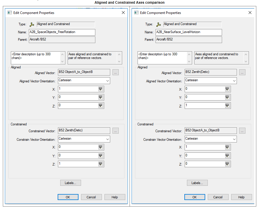
Left: If you are tracking space objects
• Aligned Vector: Click the ellipsis button for this vector and set it to To Vectors > ObjectA_to_ObjectB vector or whichever one you created.
• Aligned Vector Orientation: Set X = 1; this aims the camera. You can call it the "look vector".
• Constrained Vector: Click the ellipsis button for this vector and set it to either Object A’s zenith (detic) vector (the camera’s "up" vector) or Earth's J2000 Z vector.
• Constrained Vector Orientation: Set Z = 1.
Right: If you are near the planet surface and need the horizon line to stay level:
• Aligned Vector: Click the ellipsis button for this vector and set it to Object A’s Zenith (Detic) vector (the camera’s "up" vector).
• Aligned Vector Orientation: Set Z = 1.
• Constrained Vector: Click the ellipsis button and set it to To Vectors > ObjectA_to_ObjectB or whichever one you created.
• Constrained Vector Orientation: Set X = 1, which you use to aim the camera. You can call it the "look vector".
6. In the 3D Graphics toolbar, click the View From/To button

.
7. Select Object A, your foreground object, in both the From Position and To Position columns.
8. On the Reference Frame selector just below the two lists, click the Add… button.
9. In the left column, highlight Object A and then choose the axes you created in Analysis Workbench from under the My Components folder and click OK.
10. Zoom in on Object A and manually swing the camera around so that Object B is clearly visible in the background. You can use the <Shift> key to position Object A off to one side and leave the other side of the window for Object B.
11. Animate your scenario. You should be watching an animation where both of your objects stay in the places you put them in the window, even as they move relative to one another. You did all this without creating a Viewpath using the 3D Camera Control toolbar.
